Introduction

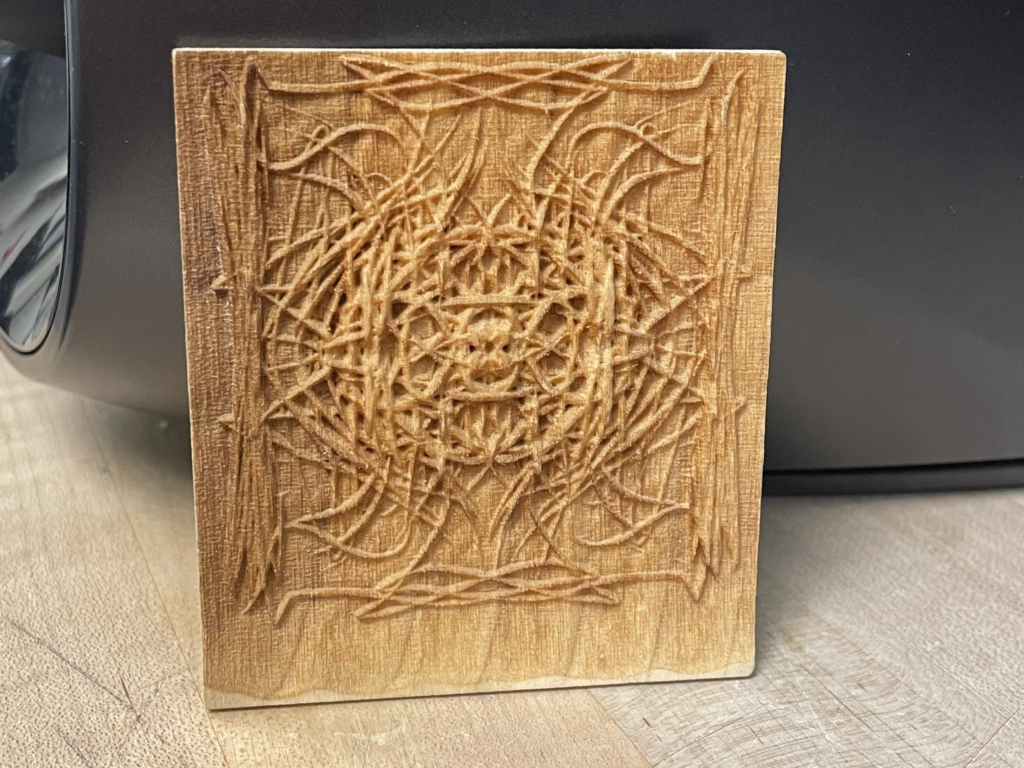
In addition to standard vector operations and raster engraving, the laser can engrave shallow 3d forms based on depth images. Normal raster engraving takes an input image and converts it into a 1-bit representation of the original image, where for each pixel, the laser is either on or off. With 3d engraving, instead of converting an image into a 1-bit representation, the laser software utilizes shades of gray to dictate the power of the laser at any given pixel. The Universal Laser Systems firmware supports 4-bit color depth or 16 distinct depth levels for an image.


Depth Images


Because everyday images and renders do not represent the distance of elements within the image, for 3d engraving we use a special sort of image called a depth image. A depth image is an image where distance from the camera in the 3d scene is communicated as a greyscale value. If the geometry is closer, it will be lighter in value, if it is further, it will be darker in value.
There are many existing depth images, intended for rendering, that can be found online to create textured surfaces. These images are often called “displacement maps” in the wild. Often they are used as one component in a Physically Based Rendering (or PBR) workflow.
Some resources for free cc0 textures are listed below:
You can also create your own depth image using the Z buffer pass within Rhino’s native render engine, Grasshopper, or any other software which can output a greyscale image.
Engraving
1. Rhino Setup
Once you have an image, orient it along with the rest of your geometry in the Fab Lab’s “Laser Cutter Template” file. During rasterization, the laser will raster every area of the bed where content is found. In order to save time, it is best to place images near each other or run them in separate passes. It will also be necessary to mute any layers that contain vectors or images for other operations on the material you are 3d engraving. Cyan reference geometry can be hidden by setting the print with to “NO PRINT” in the layer settings tab.

2. Print Settings
Once your file is entering the “print” command will bring up the “Print Setup” menu.
Like with normal laser processes, you will first need to set your window for printing, and ensure scale is 1:1. For 3D engraving you will also need to change the output from “Vector Output” to “Raster Output”.

3. Laser Properties
After these settings are changed, enter the “Properties” Menu.
- Within the preferences menu change the “Mode” of the printer to “3D” in the dropdown menu under the raster tab. This signals to the printer that it should interpret grayscale values as laser power rather than an absolute value dictated by color settings.
- Increase “Image Density” from 5 to 6 to increase the pixel resolution of the engraving on the y-axis. Do not increase image density above 6 as this leads to a change in printer resolution within the driver that alters the engravings aspect ratio.
- Print Direction can be changed by clicking on the icon. Optimal print direction will vary according to material and user preference. For organic materials like wood and chipboard, reversing the print direction to bottom up will help eliminate some discoloration. For more synthetic materials like acrylic, the effect is less pronounced.
- Change power and speed settings based on material. For the 3d raster are controlled by the Black color in the settings manager. In order to get the highest resolution engraving, PPI should be set to 1000. For both power and speed the settings are much more variable depending on the desired depth of engraving and the limits of the material. For 1/8 inch thick chip board and acrylic, good starting point is: using “Both” lasers, Power = 100%, Speed = 100%. Start by making small tests and carefully experiment until you have found the settings that work for you. When experimenting, be sure to note that the Lab has both 120 watt and 150 watt machines so testing is best performed on machines of equal power. A higher power with a lower speed will create a deeper cut, while a lower power and a higher speed will create a lighter cut. Some users find it preferable to run the same file several times instead of lowering speed on a high power cut.
- Once your settings are entered, proceed as you would in sending the job to the laser as you would with a normal laser job.

4. Etching
Once in the UCP software, it is important to check the time estimate which can be found to the far right in the same set of buttons as the “focus view” button used for focusing the laser. 3D engraving is often a long process so this step is necessary to ensure you will not go over the 2 hour daily limit on laser usage.

After estimating, focus your laser and begin your etching process.
If you are planning to cut a profile around your engraving, or have other operations to perform on the same material, it is important to not move the material between operations. Between operations, lightly brush the surface of your engraving to remove debris, making sure to not move your workpiece or the cutting bed within the laser cutter. Makeup brushes and other soft bristled paint brushes are ideal cleaning tools.
If you have any questions about the process please seek the help of a TA or staff. We are always happy to assist.
The Fabrication Lab is intended for the use of the faculty, staff, and students enrolled in courses at the Graduate School of Design pursuing academic work. Please see our Policies page for more information.
