Table of Contents
Template File
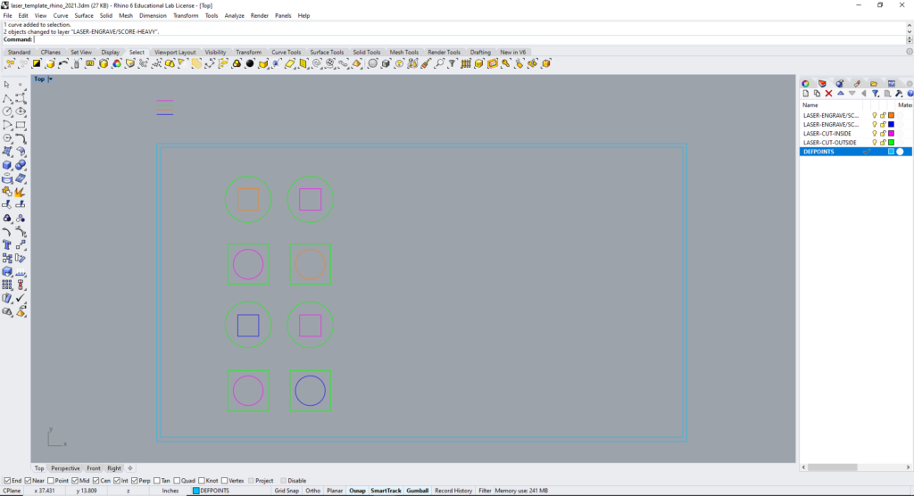
Please observe the following steps to prepare your file for laser cutting.
The file can be setup in Rhino, AutoCAD, or Adobe Illustrator.
Please use a template file, provided below and on the desktops of the laser cutter computers. This will help us troubleshoot problems should they arise.
Multiple sheets of parts to cut can be arranged in the same file. Draw a rectangular window representing the size of your material around each.
- Copy your geometry into the desired template, making sure it is scaled 1:1 to the actual size of the physical parts.
- Assign the geometry to the appropriate layer, as described in the Layer Convention Table. To minimize the movement of pieces during cutting, the layer convention is setup to:
- engrave entities before cutting them,
- cut “inside” geometry (windows) before “outside” geometry (part perimeters).
- Locate all geometry within the reference bounding boxes assigned to the “NO CUT” layer.
- Avoid creating duplicate lines, as this will cause the laser cutting to cut in the same location more than once.
- Save as a new file.
Starting Without Template File
If you are unable to use one of the above template files, please observe the following:
- Create a bounding box the size of the laser bed (32″ (X) x 18″ (Y)).
- Offset the bounding box by one-quarter of an inch, inwards, to create a margin. This margin allows some misalignment of the material to the axes of the machine.
- Create layers according to the Layer Conventions Table, below.
- Associate the curves made in steps 1 and 2 with the “NO CUT” layer, as they are for reference only.
- Proceed as though working with Template File, described above.

Layer Conventions
Files submitted to the Fabrication Lab should be setup with layers that strictly follow the order, naming, and coloring as described in the chart below:
| Order | Layer Name | Color | RGB Value |
|---|---|---|---|
| 1 | LASER-ENGRAVE/SCORE-LIGHT | Red | 255,0,0 |
| 2 | LASER-ENGRAVE/SCORE-HEAVY | Green | 0,255,0 |
| 3 | LASER-CUT-INSIDE | Yellow | 255,255,0 |
| 4 | LASER-CUT-OUTSIDE | Blue | 0,0,255 |
| 5 | NO CUT | Other | – |
Color is used to assign power and speed settings to an entity. If the color of a curve is different from that of its layer, it may not be correctly processed.
Use the exact RGB color values listed (NOT CMYK), else the laser cutter drivers will not recognize the associated geometry.
Layer order does not directly affect cut order, but it helps to communicate intent, along with layer name. The order shown above is the order the colors will be engraved or cut.
Vector Definition
As described on the Laser Cutting Methods page, only vector entities can be used to cut through the material. For an entity to be recognized as a vector, it must meet the following:
- In Rhino, all curves should be set to ‘default’ or ‘hairline’ print width.
- In AutoCAD, all curves should be set to a 0 mm lineweight.
All other entities will be treated as raster entities and can only be engraved.
The Fabrication Lab is intended for the use of the faculty, staff, and students enrolled in courses at the Graduate School of Design pursuing academic work. Please see our Policies page for more information.
